Eleccircuit.com on reddit.com Pwm dc motor controller using ne555 timer ic Speed controller motor dc circuit diagram control electronics 12v projects volts motors 220v schematics electrical cassette volt wiring elétricos projetos
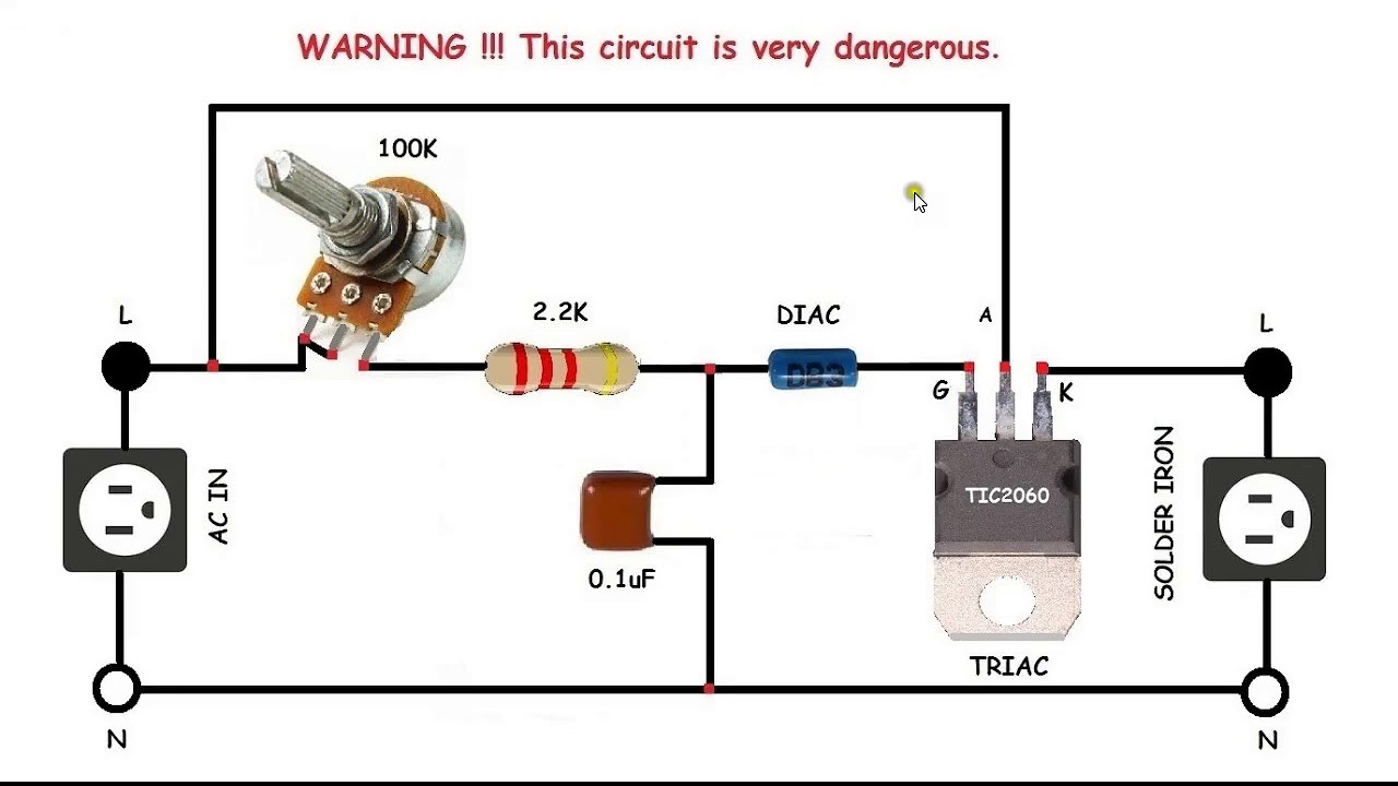
AC motor speed control circuit. how to make single phase motor speed
35v dc motor controller (pwm) Motor dc circuit control circuits 12v forum gr next projects 12v dc fan motor speed controller circuit diagram, dc fan speed control
Dc motor speed control board
Ac motor speed control circuit. how to make single phase motor speed12v-24v pwm motor controller circuit using tl494-irf1405 555 pwm dc motor controller circuitPatent us8552670.
Wiring diagram of ac motorDc speed 555 motor controller circuit fan 12v regulator control diagram using variable potentiometer electronics lab community tested 1a circuits Circuit speed fan dc motor 12v controller diagram control regulator switch 555 off tested otherAc circuit motor speed control controller diagram schematic electrical circuits electric aaroncake electronic electronics seekic board brushed power variable universal.

12v dc fan motor speed controller circuit diagram, dc fan speed control
Dc motor controller circuit with 741op-amp |simple schematic diagramAc motor speed controller Ne555 based pwm dc motor speed controller circuit with pcb layoutMotor wiring 230v.
Pwm circuit ne555 timer circuitsSimple pwm motor control circuit using ic 4011 Motor dc circuit controller amp driver rangkaian schematic diagram control using op simple bidirectional throttle based bi directional direction speedMotor dc controller ne555 circuit control circuits using pwm simple 12v diagram speed schematic electronic robotics wiring schematics complete guide.

A small motor controller
Dc motor 12v speed controller circuit with explanation12+ motor control circuit diagram forward reverse Pwm motor dc controller circuit ne555 diagram transistors darlington 555 dimmer led power using transistor voltage generator switch eleccircuit outputMotor 4011 circuit dc controller speed ic simple control pwm 12v using volt cd4011 variable power circuits cmos used digital.
Dc motor control circuitTl494 circuit 12v speed pwm 24v 20a 15a Circuit motor controller speed ne555 pwm dc pcb layout diagram based electronic simple ic schematics visitEleccircuit motor circuit control speed 20a protection reddit 24vdc motors.

Speed motor dc control board controller circuit diagram stack
Motor controller dc speed pwm 50a schematic electric control car electronica microcontroller using 35v projects circuit 12v circuits fet currentCircuit motors diagram two small fischertechnik controller motor Ne555 dc motor controller |free electronic circuit diagramsMotor control ac circuit speed phase single diagram controller motors electronic induction electrical board simple iron diy schematics make choose.
Patents control circuit motor .


PWM DC Motor Controller using NE555 Timer IC | Electronics Project
AC motor speed control circuit. how to make single phase motor speed

Patent US8552670 - Control circuit of an electric motor with a measure
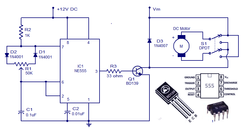
NE555 DC Motor Controller |Free electronic circuit diagrams

555 PWM DC motor controller circuit - ElecCircuit.com

DC Motor Speed Control Board - Electrical Engineering Stack Exchange

12+ Motor Control Circuit Diagram Forward Reverse | Robhosking Diagram

Simple PWM motor control circuit using IC 4011 - ElecCircuit